
Approximately 10 years ago a fellow amateur astronomer contacted me about fabricating a Unitron pier for him. Since I am a vintage telescope collector, have fabrication, welding and CAD skills, I said to myself, why not. I thought I could fabricate one for myself as well, plus I will learn a lot from this experience. From the very beginning of the conversation with this individual I offered all of my services free of charge except the CNC plasma cutting, if needed, and actual material cost. Naturally that was a big mistake on my part but as my past history reflects I seem to do just about everything for nothing. Hopefully the saying, “what goes around comes around” will come true someday.”
My first problem was finding a pier to take measurements from or finding someone that would send me accurate measurements of their pier. After searching the Internet, I found two individuals owning piers and they both were willing to help. As you may have realized, obtaining those measurements was not as easy as it may seem, especially the component that accepts the male end of the German Equatorial Mount. The unusual profile of the sweeping pier base and the tapered pier riser were also difficult to communicate their dimensional measurements. After months of correspondence back and forth I finally had enough information to model the pier in 3D. That really wasn’t going to be a problem since I have been using CAD on a daily basis since 1983 and I have a manual drafting background. Since I have a full time stressful job and work a 60 hour work week at the minimum, the time spent on this project was very limited to nights and Sunday’s, which made gathering the necessary items even more difficult.
Once I modeled everything I wasn’t that happy aesthetically with the pier. Some of the measurements just didn’t seem right. Then something magical happened. I contacted someone via email regarding a SBIG camera they were selling and ended up speaking to them on the telephone. This individual just happened to have a Unitron pier, minus the cable and weights. After some dialogue with him about Unitron scopes and the project I was undertaking, he so graciously offered to ship the pier to me if I paid for the round trip cost; therefore, allowing me to take accurate measurements. Man was I super excited. Even though I wasted several months on the project already and other individuals time trying to acquire the proper dimensional information, at least I met a few more interesting amateur astronomers. Once the pier arrived I modeled it accurately and sent it back to the original owner.
I have quite a bit of fabrication and welding experience but am an amateur machinist at best. Nearly everything I attempted to machine took a considerable amount of time due to my lack of knowledge and being a perfectionist made it even worse. Thanks to the Internet, a few machining forums I frequent, and some kind people I managed to hack away machining. I have nice vintage machining equipment and tooling but an inadequate place to actually work. So much so, I would be embarrassed to even describe it. It just goes to show what you can accomplish if you put in the effort. Thankfully I live in Arizona where the weather is nice throughout the year.
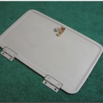
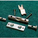
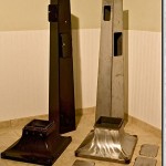
My first step was to make physical templates for the pier, therefore allowing me to make others down the road in a timely manner. The base, pier riser, and doors were hand plasma cut and TIG (Tungsten Inert Gas) welded with silicon bronze welding rod. There was extensive grinding required on this entire project. For the base and pier I used paintlock which is commonly called galvannealed. These are galvanized steel sheets that have been specially treated to allow paint to easily adhere to its surface. The very top section that accepts the GEM was made out of 6061 Aluminum and a few other items such as the door latch and spirt level mounts were made of spring phosphor bronze. If you take notice, the doors were pocketed out on the backside to mimic the original. This took a considerable amount of time considering all of my machining equipment is manually operated, no CNC unfortunately.
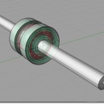
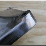
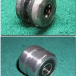
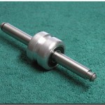
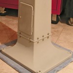
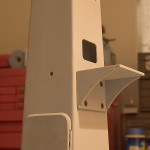
Even knurling was a learning curve for me and took some time to make it look correct, not to mention the additional tooling needed. The rounded corners of the base also mimic the original. To get that look I used some schedule 120 pipe I had laying around and cut out the circumference on all four corners to accommodate them, then TIG welded and ground them perfectly. It was necessary to fabricate a box that was welded to the inside of the base neck that accepts the pier riser, which in turn bolts together, then wrapped and TIG welded with some 3/8” round stock as trim. It gave a nice separation look where the base transitions to the riser. The clock drive shelf was another time consuming piece to make and another that needed a pocket milled on the top section. Plus since the pier is tapered, the back side of the shelf need to be milled a few degrees. One thing that doesn’t exactly match the original Unitron pier is the pulley inside the pier. It was machined to the same measurements but I wasn’t able to find a bearing to match the original so it was a little different.
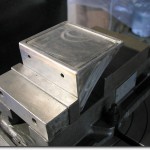
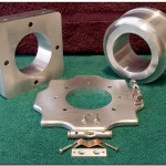
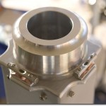
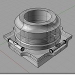
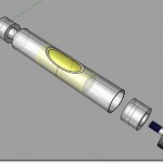
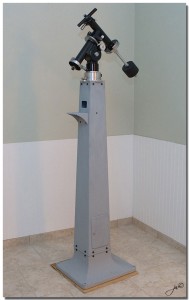
The most difficult piece for me to make and the one piece I spent a lot of time on, was the component that inserts into the top of the pier to accept the GEM. The original is one large cast piece. I decided to make the replica in 3 pieces then machine a bore in it to accept the GEM male base. So each piece was machined then assembled to appear to be one piece. I didn’t want to buy a boring bar for my Bridgeport so I found the exact center then drilled a large pilot hole in the center. After indicating the bore, I used a super long end mill with super light cuts using my Bison rotary table to make the final bore diameter. It worked perfectly but took a lot of time. The levels were all hand made as well. Obviously I didn’t make the actual bubble level, but the case and ends that encompass the levels.
I put a few primer coats on everything, made a couple of nice wooden boxes and sent everything on its merry way to the new owner. If I recall the entire setup weighed in at around 120 pounds. This was a very time consuming project. I hate to think how many hours I had in this project. I would need to check, but I am quite sure the project lasted at least six or seven months, maybe longer, after all it was about 10 years ago and I don’t recall. Cost wise tooling is super inexpensive if you purchase quality tooling which I did and then you have consumables to account for such as the silicon bronze welding rod, welding gas, grinding wheels, flapper wheels and so on. What did the entire project cost? You don’t want to know unless you are used to Roland Christen pricing.
On the down side, my computers hard-disk crashed last year and I wasn’t able to save the data on it, meaning my 3D CAD model. I also had a one terabyte backup drive that also failed. Talk about bad luck. Then the physical templates I made were lost in a fab-shop where they were left for a few days. Worst of all, I never made myself a pier.
On the positive side, I learned a lot about machining and gained an enormous respect for those in that profession, especially those still doing it manually. I wish I had started when I was much younger too. Plus, and the most important part of all is the satisfaction of making something from scratch and seeing it after completion. You know, to stand back and say I made that. I sure hated to send it to its new owner.
James Witt, October 13, 2014